The gas centrifuge represents one of the most sophisticated applications of fluid dynamics and molecular physics, allowing for the separation of isotopes with only slight differences in mass 12. This remarkable technology relies on the principles of centrifugal force to create physical separation between molecules of different masses, a process that has become essential for various applications, most notably uranium enrichment 34.
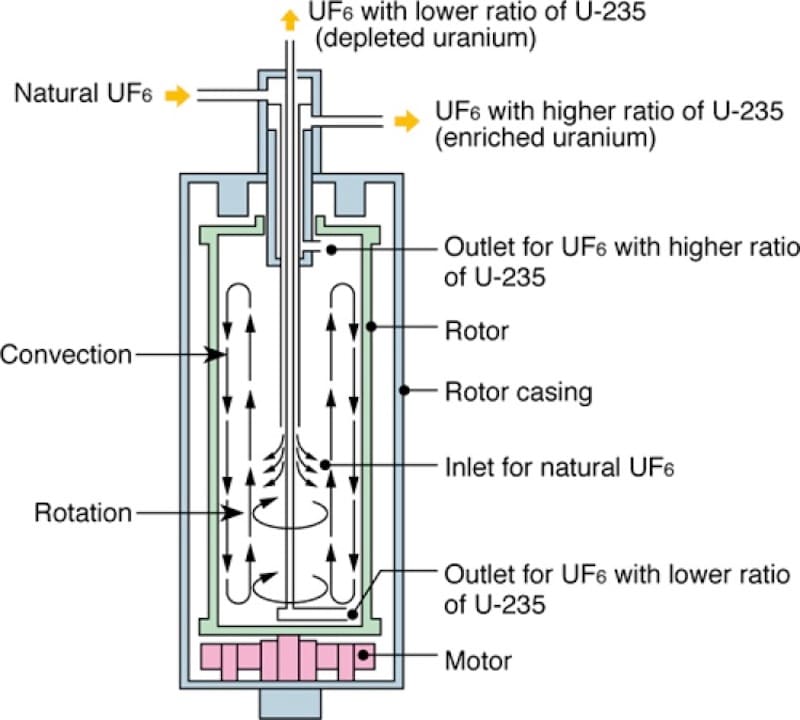
Diagram illustrating the components and gas flow within a gas centrifuge for uranium isotope separation.
Historical Development of Gas Centrifuge Technology
The concept of using centrifugal force for isotope separation was first suggested in 1919, though practical implementation faced significant challenges 2. It wasn’t until 1934 that American scientist Jesse Beams and his team at the University of Virginia successfully demonstrated the separation of chlorine isotopes using a vacuum ultracentrifuge 25.
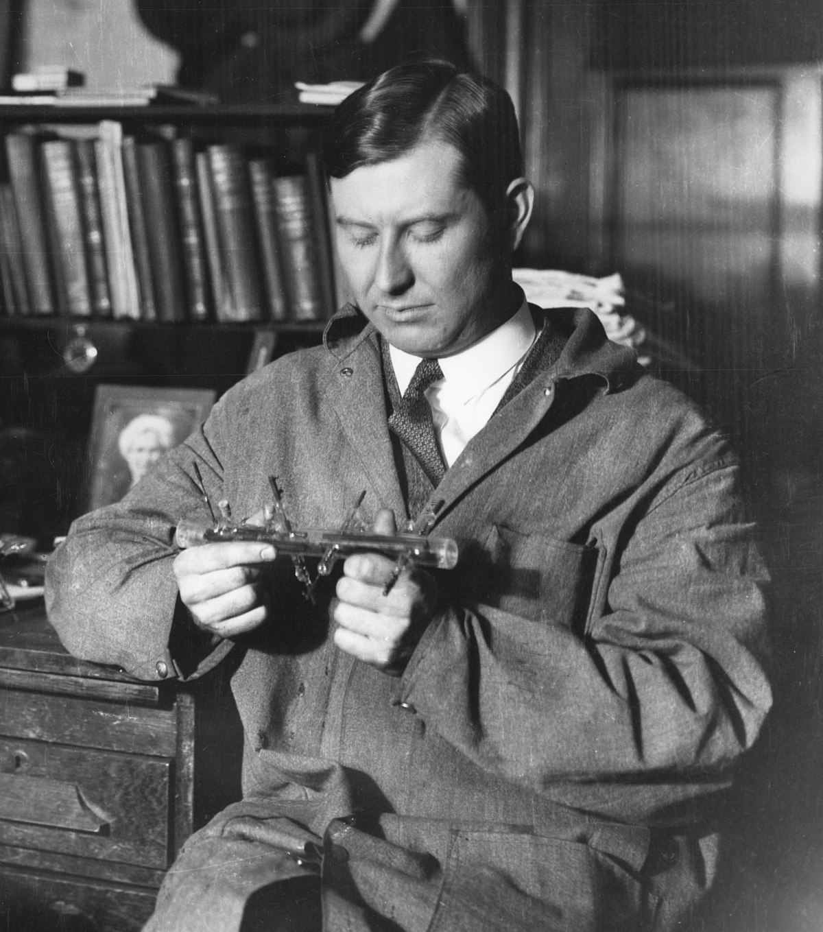
Physicist Jesse Beams examining a glass scientific apparatus, a field in which he was a pioneer.
Despite early promise, centrifuge technology was temporarily abandoned during the Manhattan Project in favor of gaseous diffusion and electromagnetic separation methods 2. The Soviet Union, however, continued developing the technology with significant contributions from German and Austrian scientists captured after World War II 67.
Among these scientists was Gernot Zippe, whose contributions would revolutionize centrifuge design 6. After returning to the West in 1956, Zippe was surprised to find that engineers in Western countries lagged behind in centrifuge technology . He recreated his design at the University of Virginia, introducing what would become known as the Zippe-type centrifuge .
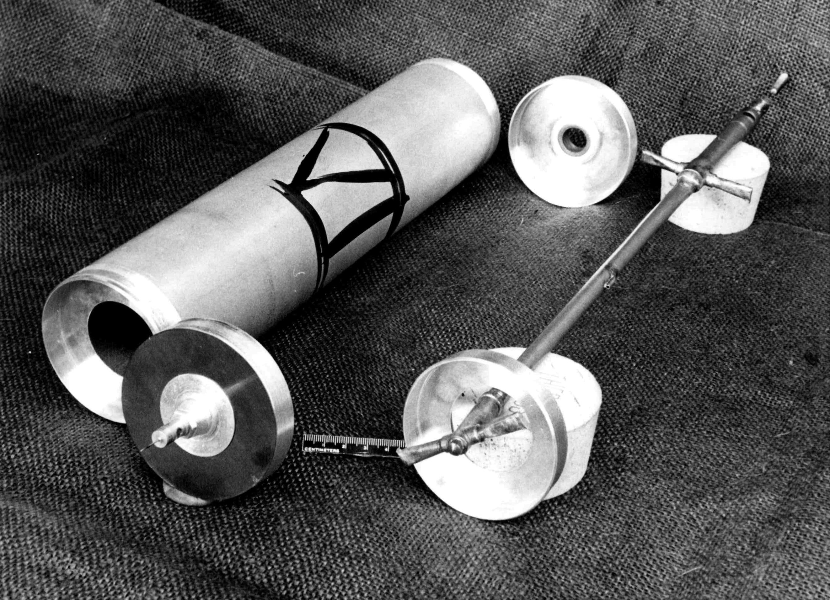
Components of a Zippe-type gas centrifuge, showing the rotor casing and internal shaft assembly.
Fundamental Physical Principles
At its core, gas centrifuge separation exploits the slight difference in mass between isotopes 1. When a cylindrical rotor containing gaseous uranium hexafluoride (UF₆) spins at extremely high speeds, the heavier molecules containing uranium-238 are forced toward the outer wall, while the lighter molecules containing uranium-235 concentrate closer to the center 23.
This separation is governed by the basic principles of centripetal acceleration 8. The centrifugal force experienced by a molecule in a rotating system is proportional to its mass, the square of the angular velocity, and the radius of rotation 910. For two isotopes with a small mass difference, this creates a subtle but exploitable separation 11.
The pressure within a centrifuge follows an exponential distribution, with near-vacuum conditions at the center axis and maximum pressure at the outer wall 1112. This pressure gradient is a direct result of the centrifugal force acting on the gas molecules 1314.
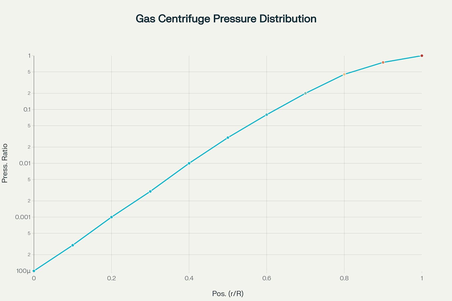
Pressure Distribution in a Gas Centrifuge
Gas Dynamics and Flow Patterns
The gas dynamics within a centrifuge are complex and involve several interrelated phenomena 1516. The primary flow pattern is the azimuthal rotation of the gas with the rotor, but secondary flows significantly enhance separation 1517.
One of the most important secondary flow patterns is the countercurrent flow, which consists of an upward movement of gas near the central axis and a downward flow near the outer wall 1819. This circulation pattern dramatically enhances separation efficiency by applying the principle of countercurrent multiplication 615.
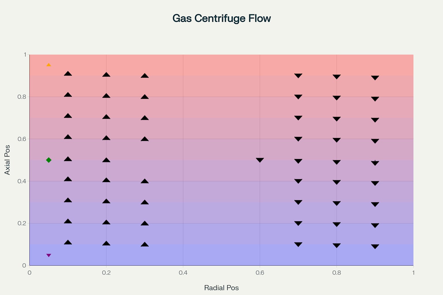
Countercurrent Flow Pattern in a Gas Centrifuge
The countercurrent flow can be induced either thermally or mechanically 6. In thermal drive, a temperature gradient is established between the top and bottom of the rotor, creating natural convection currents 2021. Mechanical drive uses specially designed scoops and baffles to induce the circulation 621.
Mathematical Models of Separation
The mathematical description of separation in a gas centrifuge involves several key equations 1322. The radial pressure distribution follows an exponential law given by:
p(r) = p(R) exp(-(Mω²/2kT)(R²-r²))
Where p is pressure, r is radial position, R is rotor radius, M is molecular mass, ω is angular velocity, k is Boltzmann’s constant, and T is temperature 1323.
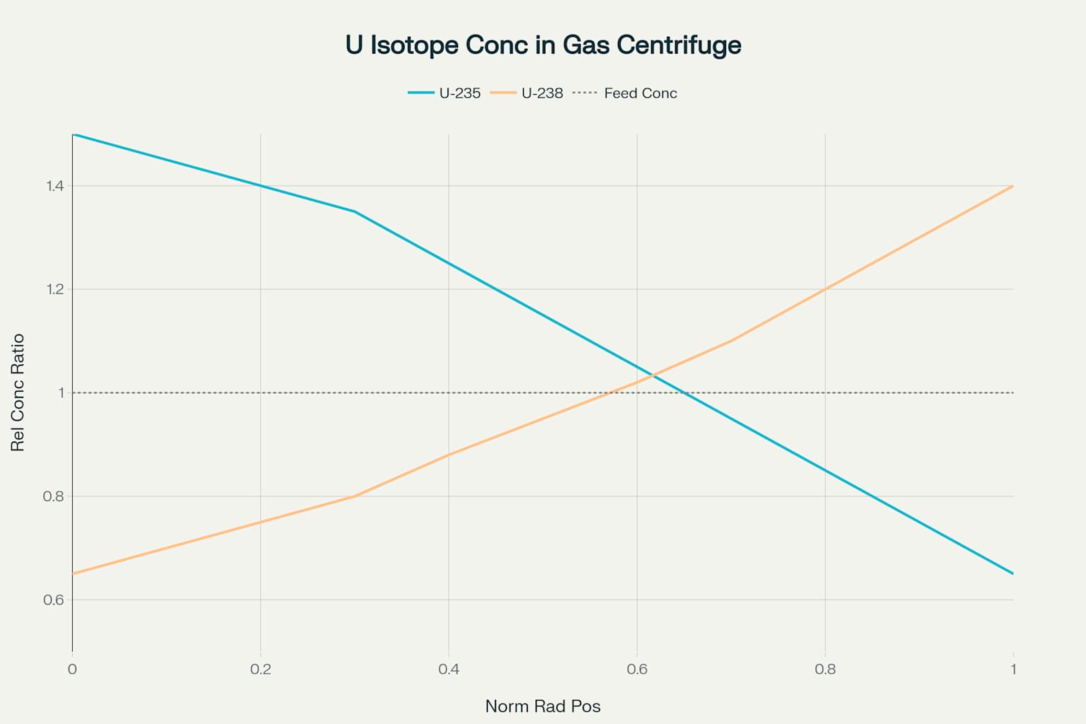
Isotope Concentration Distribution in a Gas Centrifuge
The separation factor, which quantifies the enrichment achieved, depends on both the radial separation and the enhancement from countercurrent flow 1324. For uranium isotopes, despite the small relative mass difference of only 1.26%, the absolute mass difference is sufficient to achieve practical separation when enhanced by the countercurrent effect 1323.
Theoretical models developed by Paul Dirac and later refined by Karl Cohen provide the mathematical foundation for understanding separation efficiency 1325. Onsager’s “pancake approximation” further simplified the analysis of fluid flow in gas centrifuges by treating the flow as a perturbation to solid-body rotation 26.
Centrifuge Design and Components
Modern gas centrifuges are engineering marvels, operating at the limits of material science and precision manufacturing 2728. The key components include the cylindrical rotor, motor drive system, suspension bearings, and gas handling systems 127.
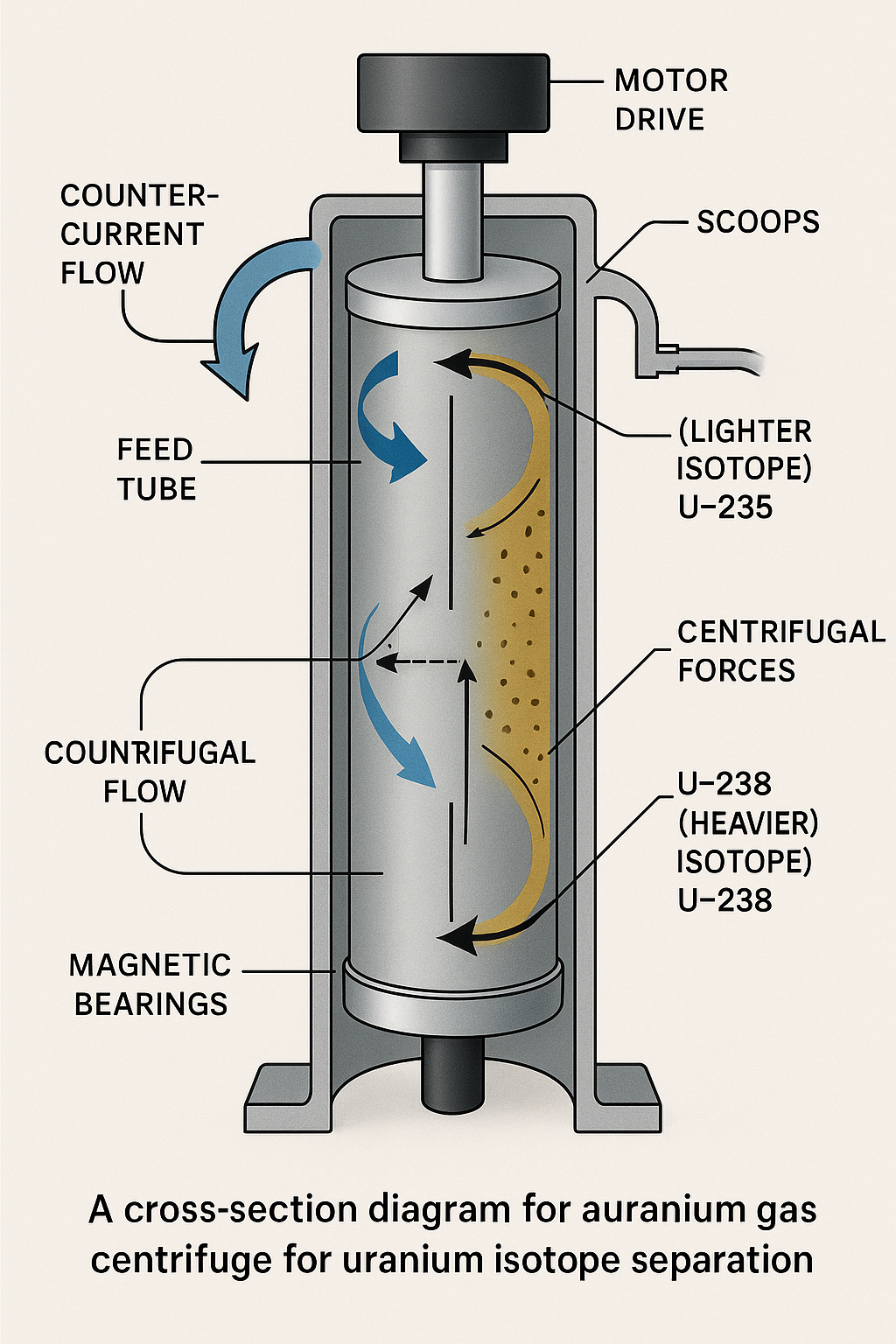
Cross-sectional diagram of a modern gas centrifuge showing the separation of uranium isotopes and countercurrent flow pattern.
The Zippe-type centrifuge introduced several revolutionary features, including a magnetic top bearing, a simple bottom needle bearing, and a molecular pump to maintain vacuum in the rotor housing 29. This design allowed for higher rotational speeds while minimizing friction and energy consumption .
The rotor material is critical to performance, as it must withstand enormous centrifugal forces 2. Early designs used aluminum, but modern centrifuges employ maraging steel or carbon fiber composites that allow peripheral speeds exceeding 500-700 m/s . These advanced materials enable longer rotors with greater throughput and efficiency 230.
Cascade Arrangements for Practical Enrichment
A single centrifuge cannot achieve the desired enrichment level and throughput for practical applications 31. Therefore, multiple centrifuges are arranged in cascades, with machines connected in series to increase enrichment level and in parallel to increase throughput 3132.
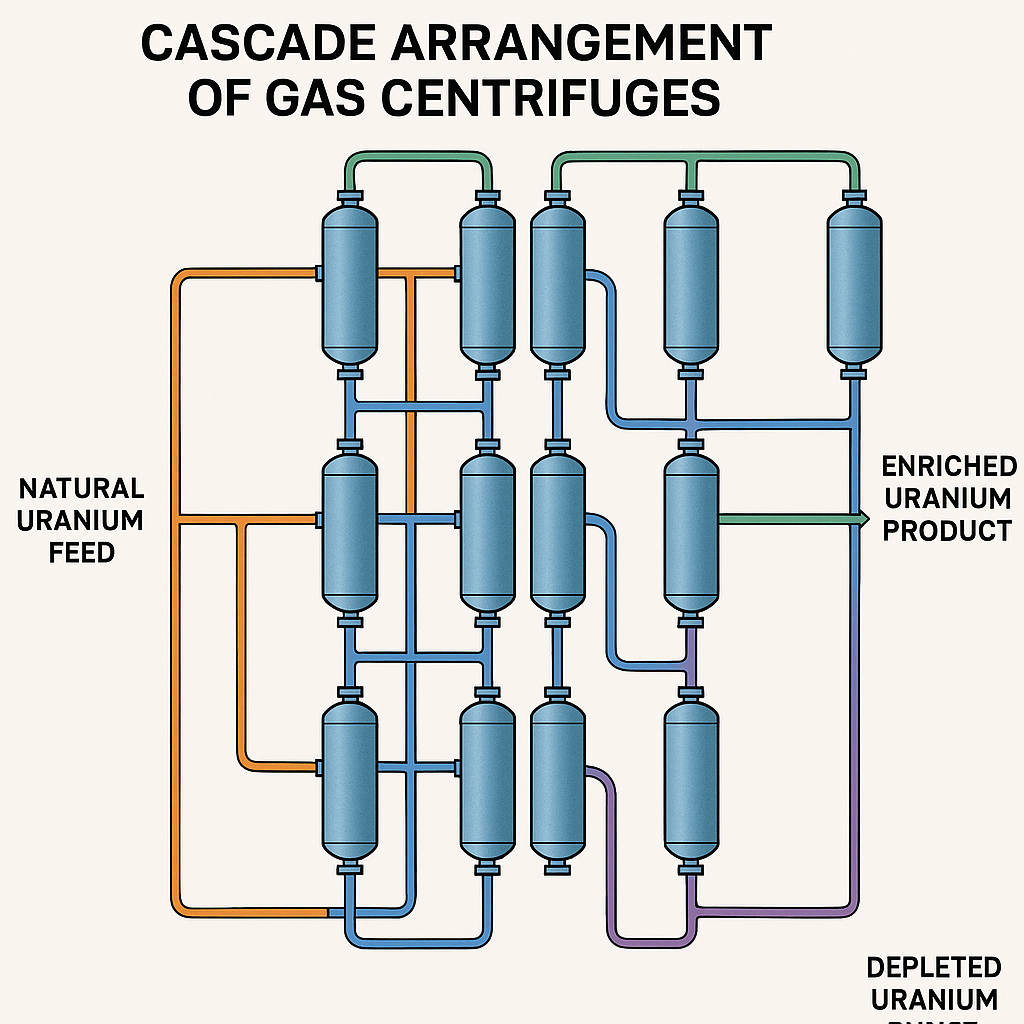
Schematic diagram of a gas centrifuge cascade arrangement for uranium enrichment showing the flow paths of feed, product, and waste streams.
The design of an optimal cascade requires balancing several factors, including separation factor, cut (the fraction of feed that becomes product), and stage efficiency 3133. The ideal cascade minimizes the total number of machines required for a given separation task 3124.
Feed material enters the cascade at an intermediate point, with product streams flowing upward to higher enrichment stages and waste streams flowing downward to lower enrichment stages 3132. This arrangement maximizes the efficiency of the entire system by matching the concentration at each stage to the optimal operating point of the centrifuges 3334.
Industrial Implementation and Modern Facilities
Modern uranium enrichment facilities house thousands of centrifuges arranged in cascade halls 35. These facilities represent significant industrial achievements, combining advanced physics, materials science, and precision engineering 36.
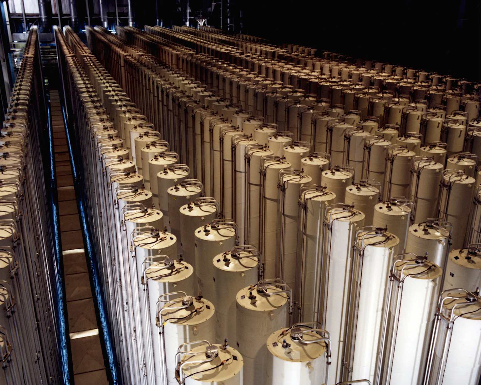
An extensive cascade of gas centrifuges within a uranium enrichment facility.
Companies like Urenco operate commercial enrichment facilities using advanced centrifuge technology 21. Their TC-21 centrifuges feature carbon fiber rotors with diameters of 20 cm and lengths exceeding 5 meters, spinning at peripheral speeds of 770 m/s .
The industrial implementation of gas centrifuge technology has evolved through multiple generations of machines 3521. Each generation has brought improvements in materials, control systems, and overall efficiency, resulting in dramatic reductions in energy consumption compared to older enrichment methods 2130.
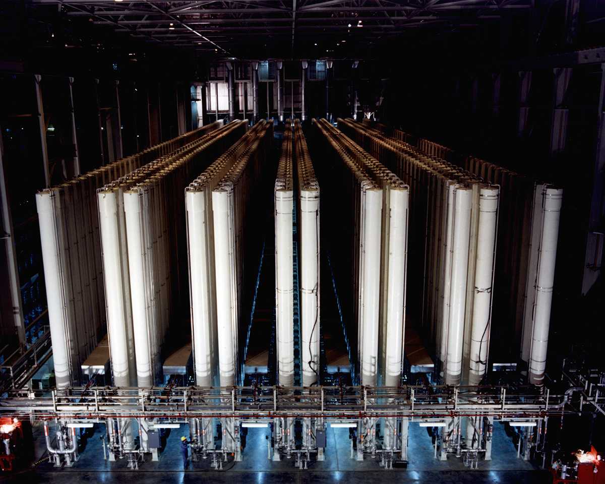
An extensive array of gas centrifuges arranged in a cascade for isotope separation.
Advantages and Technological Challenges
Gas centrifuge technology offers several significant advantages over alternative enrichment methods 27. Most notably, it consumes approximately 50 times less energy than gaseous diffusion, making it the most economically efficient enrichment process 1221.
The high separation factor of centrifuges (1.2-1.5 compared to 1.004 for gaseous diffusion) means fewer stages are required to achieve a given enrichment level 67. This results in smaller facilities with reduced uranium inventory and faster equilibrium times 75.
However, centrifuge technology presents unique challenges 27. Operating at extremely high rotational speeds requires precision balancing and careful management of vibrations, particularly when traversing critical resonance frequencies 26. Material constraints and the need to prevent UF₆ condensation also impose operational limitations 12.
Conclusion
The physics of separation in gas centrifuges represents a remarkable confluence of fluid dynamics, molecular physics, and engineering 12. From the foundational work of pioneers like Jesse Beams to modern industrial facilities with thousands of high-performance machines, centrifuge technology has evolved into the dominant method for isotope separation 25.
The complex interplay of centrifugal forces, pressure gradients, and countercurrent flows within these devices creates an environment where molecules with only slight mass differences can be effectively separated 1511. This capability has profound implications for nuclear energy, medicine, and various scientific applications 15.
As materials science and computational fluid dynamics continue to advance, we can expect further improvements in centrifuge efficiency and performance 1730. These developments will build upon the fundamental physical principles that have made gas centrifuges such a powerful and versatile separation technology 1314.
Footnotes
-
https://www.osti.gov/opennet/manhattan-project-history/Processes/UraniumSeparation/centrifuges.html ↩ ↩2 ↩3 ↩4 ↩5
-
https://en.wikipedia.org/wiki/Gas_centrifuge ↩ ↩2 ↩3 ↩4 ↩5 ↩6 ↩7 ↩8 ↩9 ↩10
-
https://www.scitechnol.com/peer-review/gas-centrifuge-an-important-technology-for-uranium-enrichment-g5mv.php?article_id=26052 ↩
-
https://energyeducation.ca/encyclopedia/Gas_centrifuge_for_uranium_enrichment ↩ ↩2 ↩3 ↩4 ↩5
-
https://pubs.aip.org/physicstoday/article/61/9/40/413428/The-gas-centrifuge-and-nuclear-weapons ↩ ↩2 ↩3 ↩4 ↩5 ↩6 ↩7
-
https://www.sigmaaldrich.com/US/en/technical-documents/technical-article/protein-biology/protein-pulldown/centrifugation-basics ↩
-
https://ccnmtl.columbia.edu/projects/biology/lecture5/protseps.html ↩
-
https://www.princeton.edu/~aglaser/2008aglaser_sgsvol16.pdf ↩ ↩2 ↩3
-
https://programs.fas.org/ssp/nukes/fuelcycle/centrifuges/separation_theory.html ↩ ↩2 ↩3 ↩4 ↩5 ↩6 ↩7
-
https://www.cambridge.org/core/journals/journal-of-fluid-mechanics/article/abs/fluid-dynamics-and-mass-transfer-in-a-gas-centrifuge/613832437D1178DF3E0C86FA238487C4 ↩ ↩2 ↩3 ↩4
-
https://www.cambridge.org/core/journals/journal-of-fluid-mechanics/article/fluid-dynamics-and-mass-transfer-in-a-gas-centrifuge/613832437D1178DF3E0C86FA238487C4 ↩
-
https://handwiki.org/wiki/Physics:Zippe-type_centrifuge ↩ ↩2
-
https://www.sciencedirect.com/science/article/pii/0149197081900263 ↩
-
https://avestia.com/MHMT2024_Proceedings/files/paper/ENFHT/ENFHT_331.pdf ↩
-
https://enritec.com/technology/centrifuge-technology/ ↩ ↩2 ↩3 ↩4 ↩5 ↩6
-
https://www.jstage.jst.go.jp/article/jnst1964/25/8/25_8_649/_pdf ↩
-
https://citeseerx.ist.psu.edu/document?repid=rep1\&type=pdf\&doi=c87fe12c68cc0e8628ed09a57c2e26a2240346a8 ↩ ↩2
-
https://marathonblainville.com/userfiles/files/57805812562.pdf ↩
-
https://www.sciencedirect.com/topics/engineering/centrifugal-separation ↩
-
https://blog.nuclearsecrecy.com/2012/05/28/zippes-centrifuges/ ↩ ↩2 ↩3
-
https://programs.fas.org/ssp/nukes/fuelcycle/centrifuges/cascades.html ↩ ↩2 ↩3 ↩4 ↩5
-
https://www.hellenicaworld.com/Science/Physics/en/GasCentrifuge.html ↩ ↩2
-
https://www.sipri.org/sites/default/files/files/books/SIPRI83Krass/SIPRI83Krass06.pdf ↩ ↩2
-
https://papers.ssrn.com/sol3/papers.cfm?abstract_id=4095167 ↩