Gas centrifuges represent one of the most efficient technologies for uranium enrichment, playing a crucial role in the production of nuclear fuel for power plants worldwide 12. These sophisticated machines utilize the principles of centrifugal force to separate uranium isotopes based on their slight mass differences 34.
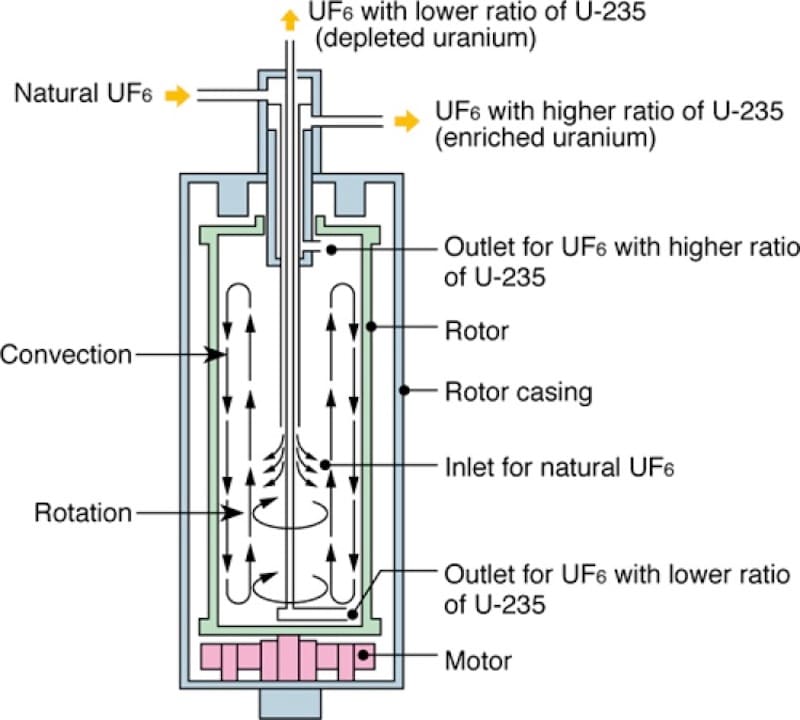
Diagram illustrating the internal workings of a gas centrifuge for uranium isotope separation, showing the flow of natural, enriched, and depleted uranium hexafluoride.
The Need for Uranium Enrichment
Natural uranium consists predominantly of two isotopes: uranium-238 (99.3%) and uranium-235 (0.7%) 35. For most nuclear reactors, the concentration of U-235 must be increased to between 3% and 5% to sustain a nuclear chain reaction 67.
This enrichment process poses a significant technical challenge because the two isotopes are chemically identical and differ in mass by only about 1.26% 89. This small mass difference requires sophisticated separation techniques to achieve practical enrichment levels 31.
The Physics of Centrifugal Separation
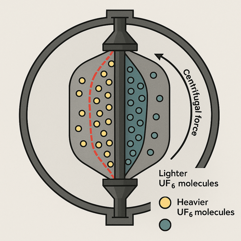
The gas centrifuge leverages basic physical principles to accomplish the complex task of isotope separation 14. At its core, the process relies on the fact that when spun at high speeds, heavier molecules experience a stronger centrifugal force than lighter ones 1011.
When a mixture containing both U-235 and U-238 is rotated rapidly, the heavier U-238 molecules are pushed more strongly toward the outer wall of the container, while the lighter U-235 molecules concentrate relatively closer to the center 39.
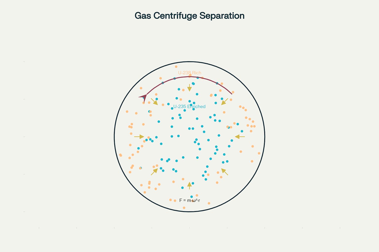
Physics diagram showing how centrifugal force separates uranium isotopes in a gas centrifuge
The centrifugal force in a spinning cylinder is directly proportional to the mass of the particle, the radius from the center, and the square of the angular velocity 1112. This relationship explains why extremely high rotation speeds are necessary to achieve effective separation of uranium isotopes 68.
Uranium Hexafluoride: The Working Medium
For uranium to be processed in a gas centrifuge, it must first be converted into a gaseous form 1314. Uranium hexafluoride (UF₆) is the compound of choice because it’s one of the few uranium compounds that can exist as a gas at relatively low temperatures 1315.
At atmospheric pressure, UF₆ sublimates at approximately 56.5°C, transitioning directly from solid to gas 1613. This property allows it to be handled as a gas during the enrichment process, while being stored as a solid 1416.
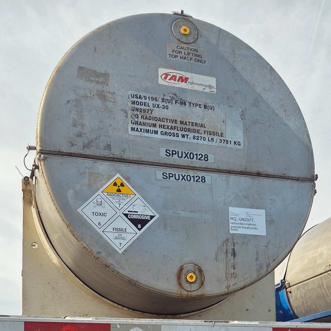
A robust cylindrical container labeled for the transport of Uranium Hexafluoride (UF6), the material used in gas centrifuges for uranium enrichment.
UF₆ is a highly reactive compound that requires careful handling due to its chemical properties 1715. It reacts violently with water and is corrosive to many materials, creating significant safety challenges in enrichment facilities 1713. Despite these hazards, its unique physical properties make it irreplaceable for gas centrifuge enrichment 1516.
Inside a Gas Centrifuge: Structure and Components
A modern gas centrifuge consists of a thin-walled cylindrical rotor that spins at extremely high speeds within an evacuated casing 1819. The rotor is typically made from high-strength materials like maraging steel or carbon fiber composites to withstand the tremendous centrifugal forces 918.
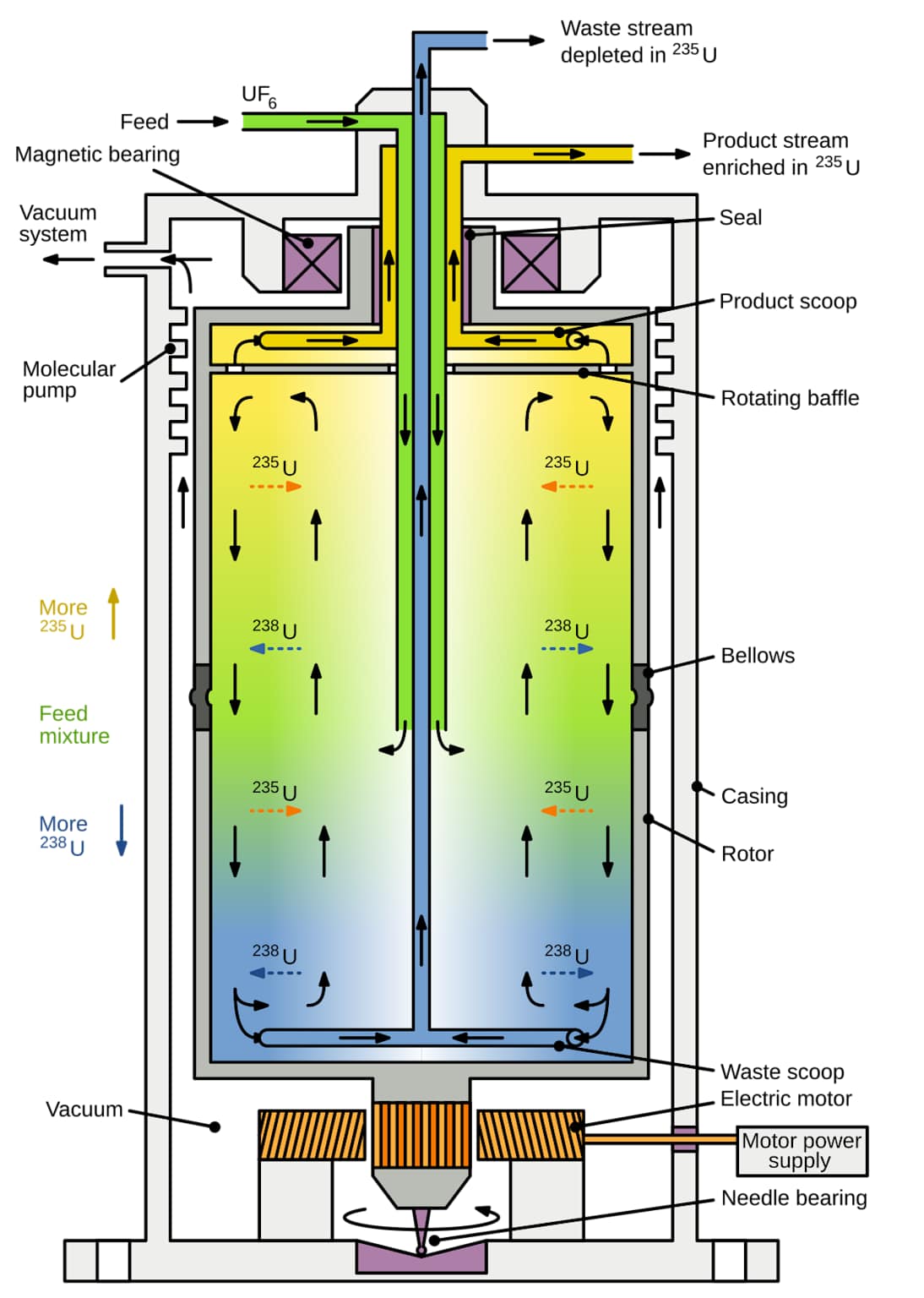
Schematic diagram illustrating the internal workings of a gas centrifuge and the separation of uranium isotopes for enrichment.
The basic components of a gas centrifuge include:
- The rotor: A tall cylindrical tube that rotates at high speed 1018
- Electric motor: Powers the rotation, usually positioned at the bottom 188
- Magnetic bearings: Support the top of the rotor with minimal friction 188
- Needle bearing: Supports the bottom of the rotor 189
- Feed, product, and waste scoops: Collect and distribute the gas 1910
- Vacuum casing: Surrounds the rotor to eliminate air resistance 184
Modern centrifuges operate at incredible rotational speeds—between 50,000 to 70,000 rpm (revolutions per minute), with the outer edge traveling faster than the speed of sound 68. These extreme speeds are necessary to achieve effective separation of the uranium isotopes 84.
The Separation Process in Action
When UF₆ gas is fed into the spinning rotor, the centrifugal force immediately begins pushing the heavier U-238 molecules toward the outer wall 1920. This creates a radial concentration gradient with U-238 enriched at the periphery and U-235 relatively concentrated toward the center 320.
Molecular separation inside a gas centrifuge showing uranium-235 and uranium-238 hexafluoride molecules
While this radial separation is the primary mechanism, modern centrifuges enhance the effect through axial countercurrent flow within the rotor 110. This is created either by a temperature difference between the top and bottom of the centrifuge or by specially designed baffles and scoops 104.
The countercurrent flow multiplies the separation effect by carrying the slightly enriched gas upward through the center and the depleted gas downward along the walls 310. This combined radial and axial separation allows a single centrifuge to achieve a higher separation factor than would be possible with radial separation alone 109.
Cascade Systems: Achieving Higher Enrichment
A single centrifuge can only achieve a small degree of separation in one pass, increasing the U-235 concentration from perhaps 0.7% to around 1.4% 217. To reach the 3-5% enrichment needed for reactor fuel, multiple centrifuges must be connected in series and parallel arrangements called cascades 722.
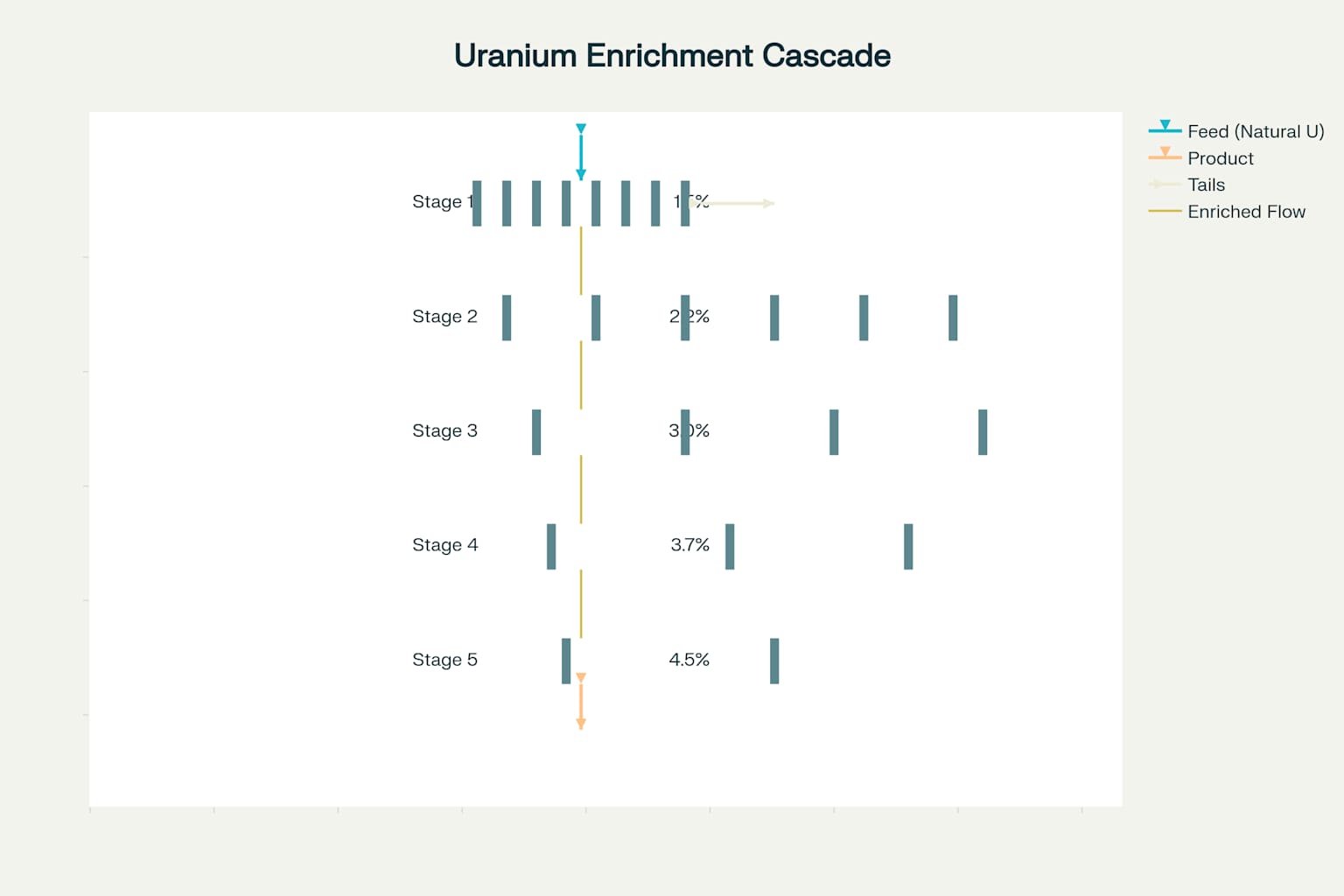
Uranium enrichment cascade system showing multiple centrifuges arranged to progressively increase U-235 concentration
In a cascade configuration, the slightly enriched output from one centrifuge becomes the input for the next, progressively increasing the concentration of U-235 27. Meanwhile, the depleted streams are recycled backward through the cascade to maximize efficiency and recovery 227.
The design of these cascades is a complex engineering challenge, balancing factors like separation efficiency, energy consumption, and uranium recovery 2223. Large commercial enrichment facilities may contain thousands of centrifuges arranged in multiple cascade halls 232.
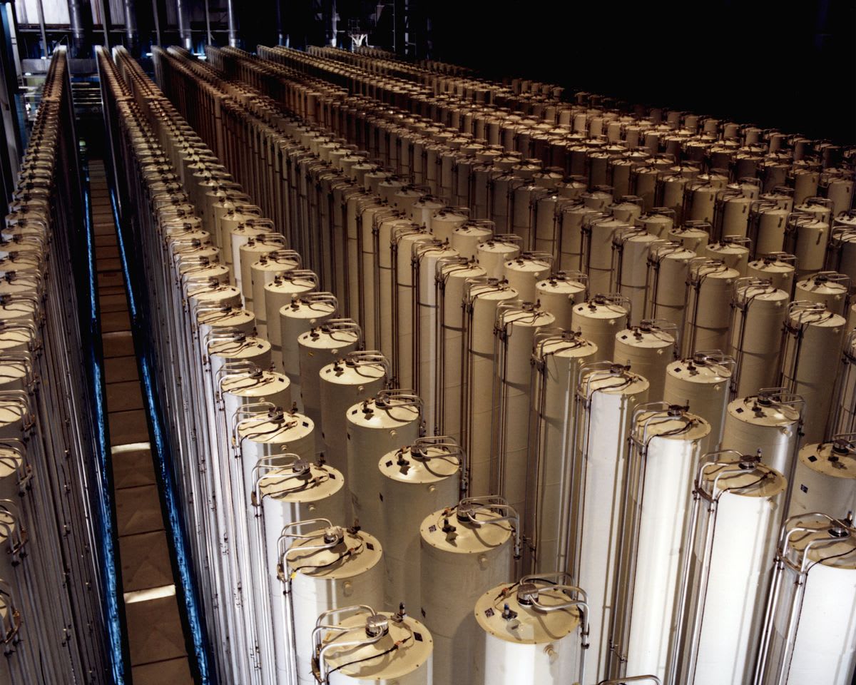
Rows of gas centrifuges in a cascade configuration for uranium enrichment.
Industrial-Scale Enrichment Facilities
Modern uranium enrichment plants are massive industrial complexes housing thousands of centrifuges operating in carefully controlled environments 2324. These facilities require extensive supporting infrastructure, including systems for gas handling, cooling, control, and monitoring 236.
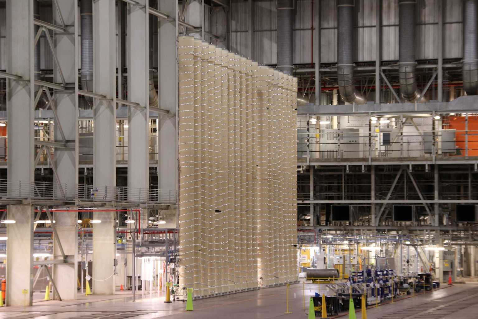
A large-scale gas centrifuge cascade within an industrial hall, demonstrating the setup for uranium enrichment.
The centrifuges are typically arranged in cascade halls, with each hall containing multiple cascades 2423. The physical layout of these facilities is designed to maximize efficiency while ensuring operational safety and security 2325.
A typical large-scale enrichment plant can produce enough enriched uranium to fuel dozens of nuclear power plants, representing a significant industrial investment 67. The largest facilities can produce millions of SWU (Separative Work Units) annually, a measure of the effort required for enrichment 216.
Historical Development of Centrifuge Technology
The concept of using centrifugal force for isotope separation was first suggested in 1919, but practical implementation proved challenging 19. The first successful uranium enrichment by centrifuge was achieved in the 1930s by Jesse Beams at the University of Virginia 118.
During World War II, both the Manhattan Project in the United States and scientists in the Soviet Union explored centrifuge technology 19. However, the Americans ultimately focused on gaseous diffusion for the wartime effort, while the Soviets continued centrifuge development 125.
A major breakthrough came with the development of the Zippe-type centrifuge in the 1950s by German scientist Gernot Zippe while working in the Soviet Union 91. This design incorporated many innovations that form the basis of modern centrifuges, including magnetic bearings and molecular pumps 918.
Safety and Environmental Considerations
The operation of gas centrifuge facilities involves several significant safety and environmental considerations 2627. The primary hazards include the handling of UF₆, which reacts violently with moisture to form corrosive and toxic hydrogen fluoride 1727.
Centrifuge facilities implement extensive safety systems to prevent and contain potential releases 2829. These include specialized containment structures, detection systems, and emergency response protocols 2930.
From an environmental perspective, centrifuge enrichment is significantly more energy-efficient than older gaseous diffusion technology, requiring only about 2-5% as much electricity to produce the same amount of enriched uranium 206. This reduced energy consumption translates to a smaller carbon footprint for the nuclear fuel cycle 266.
Security and Proliferation Concerns
The same technology that efficiently produces fuel for civilian nuclear power also has implications for nuclear weapons proliferation 251. Highly enriched uranium (>90% U-235) can be used in nuclear weapons, and centrifuge technology could potentially be adapted for this purpose 251.
For this reason, centrifuge technology is subject to strict international controls and safeguards 252. Enrichment facilities are regularly inspected by the International Atomic Energy Agency (IAEA) to verify that they are being used exclusively for peaceful purposes 252.
The technical characteristics of centrifuges present unique nonproliferation challenges 251. Their relatively small size, low energy consumption, and potential for concealment make them more difficult to detect than other enrichment technologies if used covertly 2526.
Maintenance and Operational Challenges
Maintaining gas centrifuges presents unique challenges due to their extreme operating conditions 3130. The rotors spin at such high speeds that even tiny imbalances can cause catastrophic failures 3028.
Regular maintenance includes inspection for signs of wear or corrosion, particularly in the bearing systems 3129. However, once operational, centrifuges typically run continuously for years without stopping, as the stress of repeated starts and stops can damage the precision components 3128.
The intense rotational forces mean that rotors must be made of specialized materials with exceptional strength-to-weight ratios 98. Earlier centrifuges used aluminum, but modern designs employ maraging steel or carbon fiber composites that allow for higher speeds and better separation efficiency 98.
Conclusion
Gas centrifuges represent a remarkable engineering achievement that applies basic physical principles to solve the complex problem of isotope separation 13. Their development has revolutionized uranium enrichment, making it more efficient, economical, and accessible 206.
As the primary technology for uranium enrichment worldwide, gas centrifuges play a vital role in the nuclear fuel cycle that powers a significant portion of global electricity generation 67. Understanding how these sophisticated machines work provides insight into both the technical challenges and the strategic implications of nuclear technology 251.
The science of spinning uranium exemplifies how ingenious engineering solutions can harness fundamental physical principles to achieve what once seemed impossible: the separation of nearly identical atoms based solely on their minuscule mass difference 38.
Footnotes
-
https://en.wikipedia.org/wiki/Gas_centrifuge ↩ ↩2 ↩3 ↩4 ↩5 ↩6 ↩7 ↩8 ↩9 ↩10 ↩11 ↩12 ↩13 ↩14
-
https://www.nrc.gov/materials/fuel-cycle-fac/ur-enrichment.html ↩ ↩2 ↩3 ↩4 ↩5
-
https://energyeducation.ca/encyclopedia/Gas_centrifuge_for_uranium_enrichment ↩ ↩2 ↩3 ↩4 ↩5 ↩6 ↩7 ↩8
-
https://www.hellenicaworld.com/Science/Physics/en/GasCentrifuge.html ↩ ↩2 ↩3 ↩4 ↩5
-
https://world-nuclear.org/information-library/nuclear-fuel-cycle/conversion-enrichment-and-fabrication/uranium-enrichment ↩ ↩2 ↩3 ↩4 ↩5 ↩6 ↩7 ↩8 ↩9 ↩10
-
https://www.centrusenergy.com/learn-more/nuclear-fuel-cycle/enrichment/ ↩ ↩2 ↩3 ↩4 ↩5 ↩6 ↩7
-
https://www.liquisearch.com/zippe-type_centrifuge/centrifuge_uranium_enrichment ↩ ↩2 ↩3 ↩4 ↩5 ↩6 ↩7 ↩8 ↩9
-
https://en.wikipedia.org/wiki/Zippe-type_centrifuge ↩ ↩2 ↩3 ↩4 ↩5 ↩6 ↩7 ↩8 ↩9 ↩10 ↩11
-
https://www.nrc.gov/docs/ML1204/ML12045A055.pdf ↩ ↩2 ↩3 ↩4 ↩5 ↩6 ↩7
-
https://fd-separators.com/Understanding-Centrifugal-Inertia-and-Separation-Efficiency.html ↩ ↩2
-
https://en.wikipedia.org/wiki/Uranium_hexafluoride ↩ ↩2 ↩3 ↩4
-
https://energyeducation.ca/encyclopedia/Uranium_hexafluoride ↩ ↩2
-
https://www.wnti.co.uk/wp-content/uploads/2021/09/WNTI_Fact_Sheet_UF6_v3.pdf ↩ ↩2 ↩3
-
https://www.energy.gov/sites/prod/files/2020/11/f80/SDS-Uranium_Hexafluoride_UF6_2020.pdf ↩ ↩2 ↩3
-
https://www.youtube.com/watch?v=LxvtGHdCVtE ↩ ↩2 ↩3 ↩4 ↩5 ↩6 ↩7 ↩8 ↩9
-
https://www.centrusenergy.com/learn-more/uranium-enrichment/gas-centrifuge/ ↩ ↩2 ↩3
-
https://enritec.com/technology/centrifuge-technology/ ↩ ↩2 ↩3 ↩4
-
https://energyeducation.ca/encyclopedia/Separative_work_unit ↩ ↩2
-
https://isis-online.org/uploads/isis-reports/documents/WCWitt__Modeling_Irans_Tandem_Cascade_Configuration_for_Uranium_Enrichment_by_Gas_Centrifuge.pdf ↩ ↩2 ↩3
-
https://www.nrc.gov/docs/ML0421/ML042190034.pdf ↩ ↩2 ↩3 ↩4 ↩5 ↩6
-
http://www.princeton.edu/~aglaser/2007aglaser_splg.pdf ↩ ↩2 ↩3 ↩4 ↩5 ↩6 ↩7 ↩8 ↩9
-
https://ehs.stanford.edu/reference/centrifuge-safety ↩ ↩2 ↩3
-
https://www.ehs.uci.edu/sop/hazardous-operations/centrifuge-sop.pdf ↩ ↩2 ↩3
-
https://www.osha.gov/sites/default/files/publications/OSHAquickfacts-lab-safety-centrifuges.pdf ↩ ↩2 ↩3
-
https://newlifescientific.com/blogs/new-life-scientific-blog/centrifuge-care-and-maintenance ↩ ↩2 ↩3